Now that we've looked through Boolean Algebra, we are going to take a leap into the world of schematics and more advanced logic. To begin with, you need to know the schematic symbols for our combinational logic circuits. Here are the key ones you should know:
| * | = AND |
| + | = OR |
| ! | = NOT |
| (+) | = XOR |
You see here a new symbol as well--XOR. When two numbers are XOR'd they answer is only 1 if 1 or the other is 1, not both, pretty easy. From these we will build more complex parts like adders and multiplexors. Instead of re-writing the entire circuit as we go along, we will place these in a square box with their name. You will see this as we go along.
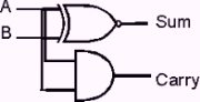
Okay then, time to build our first circuit, a half adder. This is a circuit that will add 2 binary numbers together, ignoring the possibility of a carry in. The lack of ability to handle a carry gives it its name. The theory behind a half adders logic is pretty basic. There are two inputs, binary number A, and binary number B. Also, there are two outputs, Sum and Carry. Now let's use what is called a truth table to look at what the values of each number should be. We begin by making a truth table that has every possible input combination, like this:
  A  |  B  | Sum | Carry
-------------------------
  0  |  0  |     |
  0  |  1  |     |
  1  |  0  |     |
  1  |  1  |     |
Next, we fill out what the "answers" to our problem would need to be, like this:
  A  |  B  | Sum | Carry
-------------------------
  0  |  0  |  0  |   0
  0  |  1  |  1  |   0
  1  |  0  |  1  |   0
  1  |  1  |  0  |   1
There, we have now completed our first truth table. The next stage, is to develop a formula to figure out which combinations give us our desired values. First let us look at Sum. Sum is equal to one only when A or B is equal to 1, but not both. This sounds just like a XOR gate, so lets put it together in an equation-- Sum=A (*) B. Now, let's look at the Carry. The Carry is only equal to one when both A and B are equal to 1, so let's use an And gate, leaving us: Carry=A * B. Now we have the two needed equasions to make the circuit. Lets look at it like this-
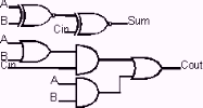
Okay, this is a good start. However, half adders are not really useful for anything other than a building block. For any real processing, we need to have a full adder that is capable of receiving a carry, as well as outputting one. The full adder works in the same way that we did the boolean math, and carried the numbers over for addition. This lets us chain them together to make a higher level (bit) implementation of the same circuit. The three inputs of the full adder will be represented as A, B, and CI (carry in). The outputs will be named S (sum) and CO (carry out). We will write sum as S = CI (+) A (+) B, and CO as CO = CI * (A + B) + A * B. Great, now lets just re-write that in schematic form:
We are now complete with learning the most basic combinational logic circuits. Although the methods of writing out the truth table and looking to discover a way of implementing the answer works, it is really not very efficient. With the more complex circuits that we will be creating, simply generating an answer without a good method does not work. That is why we use Karnough maps. Karnough maps are the basic foundation of how to develop single stage implementations of combinational logic circuits. I am going to give you a short introduction to Karnough maps, however, they take lots of practice. Because of the complexity of Karnough maps, I will show you the basic steps, and let you explore more on your own. For an excellent source to learn more, I would highly recommend purchasing Randy H. Katz's book, Contemporary Logic Design. He has excellent examples, and goes very in-depth. Well-- enough of where else to look-- Let's jump in now!!
A K-map is going to be our key for developing a foundation of pieces to use in our processor. Based on the theory of boolean truth table adjacencies, K-maps provide a simple approach to determining realizations of complex combinatational logic problems.
In order to use a K-map, we must first talk a short bit about Grey Code. This is the binary implementation where never more than a one bit shift occurs in our counting. All K-map's will be written using grey code, so that our adjacencies can be properly extracted. First, let's take a look at a simple K-map structure.
     Map of Z, as a funtion of ABC
                   AB
          00    01    11     10
      --|-----|-----|-----|-----|
      0 |     |     |     |     |
   C  --|-----|-----|-----|-----|
      1 |     |     |     |     |
This empty K-map shows us the basic setup that goes into a logic problem. Remember those old elementary logic puzzles where you filled in a grid pattern to determine a given problem? This is very similar. First, we need to pay special attention to the way that the grid is layed out. The top is representative of the A and B values, while the side is that of C. This will be easier to see when we map a problem to our K-Map. Let's use the following truth table to develop a function for.
A, B, and C are inputs, while Z is our output.

   A  |  B  |  C  ||  Z
  ----|-----|-----||----
   0  |  0  |  0  ||  1
   0  |  0  |  1  ||  0
   0  |  1  |  0  ||  1
   0  |  1  |  1  ||  0
   1  |  0  |  0  ||  0
   1  |  0  |  1  ||  1
   1  |  1  |  0  ||  0
   1  |  1  |  1  ||  1
Alright, now let's take that truth table, and map the Z's into our K-map based on their A, B and C values.
                   AB
          00    01    11     10
      --|-----|-----|-----|-----|
      0 |  1  |  1  |  0  |  0  |
   C  --|-----|-----|-----|-----|
      1 |  0  |  0  |  1  |  1  |
Perfect. You can now see that our function, Z, is equal to one in 4 locations. Now, lets use what is called Sum of Products form (or SOP) to determine a simple formula. We need to group our adjacent 1's in powers of 2 (ie 2, 4, 8 ...) first. This leaves us with two cirlces of grouped ones. On on the top left, the other on the bottom right. Now, just take the values for A, B, and C that make up those circles. The first (top left) is made up of A=0, and C=0. As you can see, it is 1 for both values of B, so we ignore B. We can then write the formula simply as (A'B'). We next need to look at the bottom right corner. This is made up of values A=1, C=1, or (AC). Our final formula is the sum of these to products, or (A'B')+(AC). This is equal to our Z. By grouping these adjacencies, we can determine any size problem of any type, quickly and easily.
That is really all there is to Karnough maps-- except understanding what is adjacent. You need to remember that our K-maps are really 3-d, so the top right number is adjacent to the top left, as if the map were really on a sphere. I know this will take a little getting used to, but as we do K-maps throughout the next several sections, you will pick it up quickly.
Jump Back to the Processor Design Home Page